Mad Max F1Tenth
A LiDAR-only racing controller that adapts speed and steering to track geometry — no pre-built map required.
University of Illinois Urbana-Champaign · ECE 484 · Spring 2026
Final Run
System Architecture
01 LiDAR Scan + Joystick Enable
↓
02 Front Distance · Track Width · L/R Wall Estimate
↓
03 Speed Controller + Steering PID
↓
04 Ackermann Drive Command
↓
→ Car Motion
At race time the full stack runs three things in parallel: teleop (motor + joystick enable), the LiDAR sensor node, and our race controller — which closes the loop on every scan.
Approach
Once we determined that SLAM would be infeasible for us to properly use for the competition, we began iterating on the EOH script.
Speed Controller
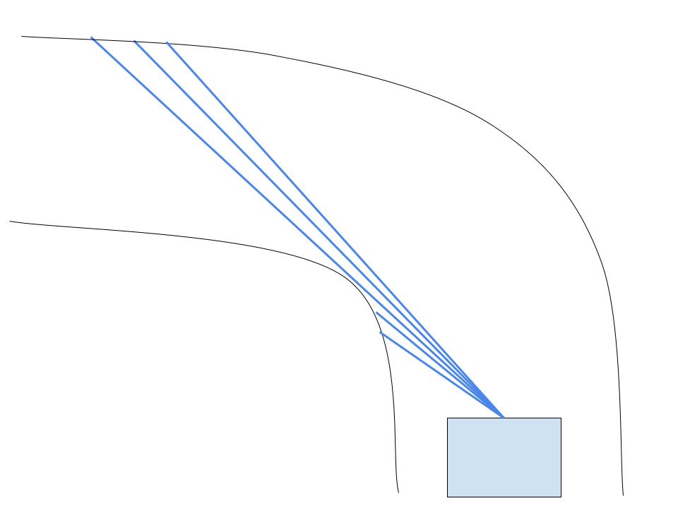
The original EOH script relied controlled the speed using the front distance to linearly control the speed. This front distance was calculated by using the minimum distance in the -10 to +10 degree cone in front of the LIDAR.
In our program, we use a narrower -5 to +5 degree cone in front of the LiDAR mitigate the effect of the LiDAR picking up the sides of the road up ahead on either side of the LiDAR.
Our main difference with the speed controller was that we also linearly scaled with the sum of the minimum distance between the left and right walls, a stand-in for road width.
We receive LIDAR inputs in an array with consecutively increasing indices corresponding to consecutively increasing degrees. We determined the point in this array that corresponded to the “barrier” between the left and right walls and then found the minimum distance within each of these points corresponding to each wall.
We scale the speed with this front distance value and the width and some constants we got from testing.
Special Cases
We keep the speed above 1.5 at all times to avoid motor stuttering. There are 3 cases in which we don’t follow this default speed value based on width and front distance:
- On startup, we set the speed to 5 for 0.33 seconds to get above the motor stuttering speed.
- If we don’t detect a wall ahead, then we fall back to a slower speed value.
- If the wall is over 13 meters ahead, then go at max speed. This is an optimization for going fast on long straights.
Steering Controller
Our steering controller is the same PID controller used in the EOH script except we tuned the coefficients. The process we used was increasing P until it was high enough to make all of the tightest turns, and then increasing D until oscillations on straights were kept to a minimum. We did not have to change I.
Evaluation & Metrics
We evaluated the controller using three main metrics: lap performance, responsiveness to sensor data, and safety metrics. Since our final approach did not rely on localization, it was important that the car could react quickly and correctly to live LiDAR data.
Sensor Responsiveness
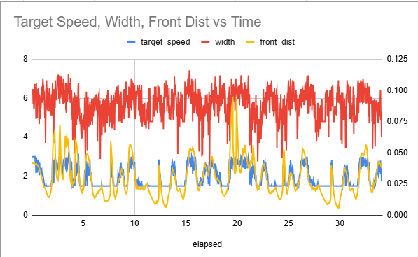
The tuning graph shows how target speed changed with front distance and steering. When the car saw more open space ahead, the target speed increased. When the track became tighter or obstacles were closer, the target speed dropped. This shows that the controller was reacting to the track in real time.
Speed Tracking and Ramping
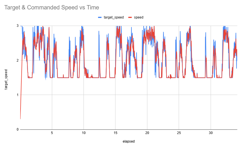
The second graph compares target speed with the actual commanded speed. These are not exactly the same because we added acceleration and deceleration ramping. Instead of instantly jumping to the target speed, the car smoothly approaches it, which made driving less jerky and more stable.
Safety Metrics
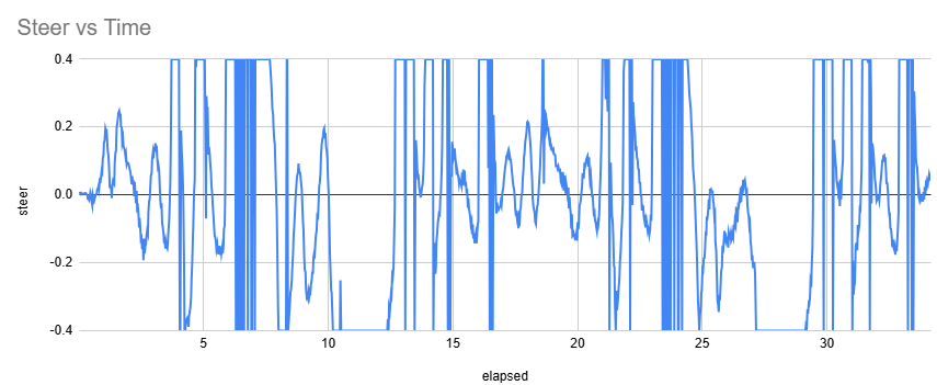
To ensure safety with the car, we decided to clip the steering angle from -0.4 to 0.4, to avoid extremely steep turns. Additionally, we specifically tuned our parameters so we would always exceed 0.3 meters to our next obstacle.
Results
Our final controller completed 3 laps in 51 seconds without any collisions. Speed adapted to open space ahead and to track width; steering used side-LiDAR readings to stay centered. The result is a controller that drives efficiently without depending on localization.
Run annotations
- 0:03 — Straight: car at max speed
- 0:07 — Turn ahead: car slows for front distance
- 0:11 — Hairpin: car slows for front distance and track width
Milestones Reached
Simulation
- Generated a SLAM map of the track
- Localized the car against the generated map in simulation
Physical Car
- Got scan matching SLAM working on the physical car
- Tuned the wall follower to traverse the track safely and reliably
SLAM (Simulator)
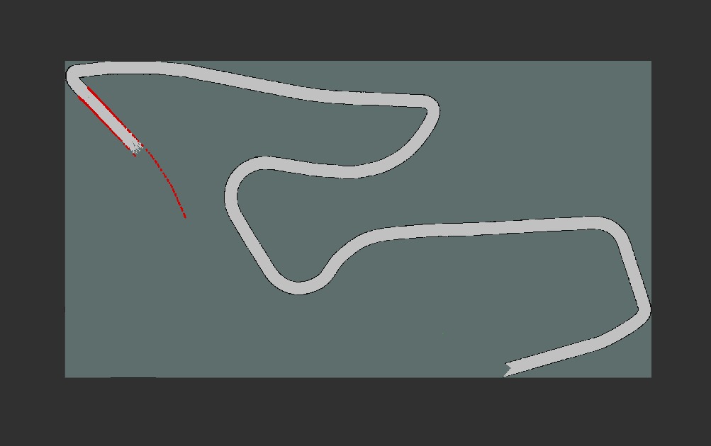
Before settling on the LiDAR-only controller, we built out SLAM mapping and AMCL localization in the F1Tenth simulator. The goal was to map a track on a formation lap and reuse the map for waypoint-based control on subsequent laps. We got both mapping and localization working in simulation — the issues only appeared when we moved to the physical car (see Challenges).
The car running SLAM on the Red Bull Ring in simulation.
Partial SLAM map mid-lap
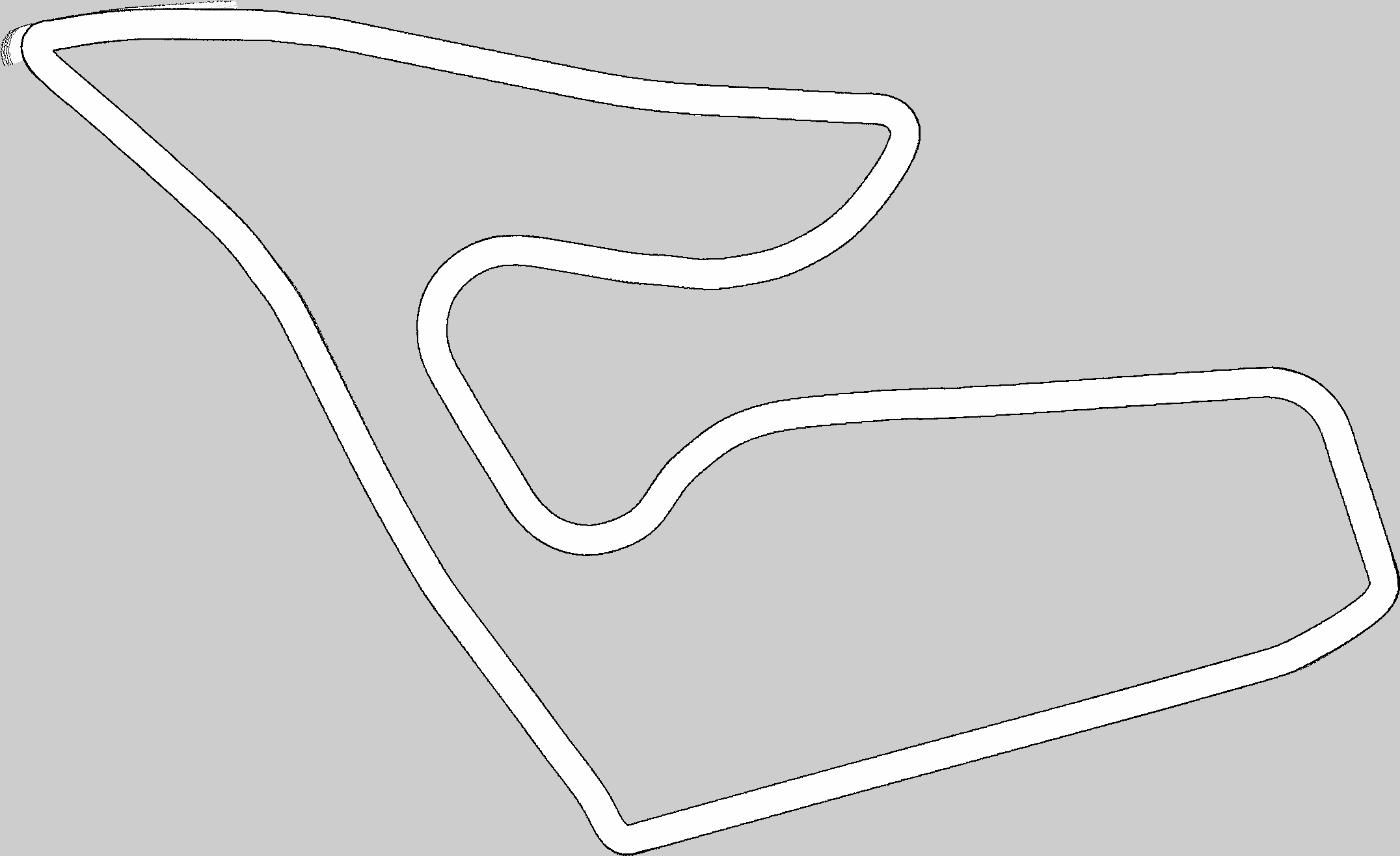
Completed SLAM map after a full lap
The car localizing on the SLAM map it generated. The green dot is the ground truth data fed by the sim and the red dot is the prediction.
Challenges
01
Motor / Starting Torque
During early testing, Car 1 had motor issues that made tuning difficult. The car often jumped or hesitated from a stop because the motors did not provide enough starting torque, which caused unstable launches.
Solution For race. Calibrate the motors for a better start.
02
SLAM Sim-to-Real Gap
We got SLAM mapping and AMCL localization working in simulation — generating a map on one track and localizing the simulated car on it.
What went wrong. This did not transfer cleanly to the physical car. The sim-to-real gap was too large, and localization wasn’t accurate enough for reliable autonomous driving.
03
Scan Matching Without Odometry
With full SLAM out of reach on the real car, we tried scan matching without odometry. It worked on small tracks (CSL studio), but failed on larger ones because loop closure became unreliable — producing map artifacting and drift.
What we tried. Cartographer and SLAM Toolbox. Neither produced reliable localization on the physical car in our setup.
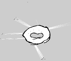
Scan matching working on a small track (CSL studio).
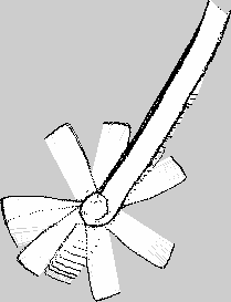
Drift and map artifacts on a larger track.
Future Work
Visual odometry A camera-based odometry source could ground SLAM enough to close loops on larger tracks.
Better wheel odometry Adding encoders would give us a clean velocity signal, removing one of the biggest sim-to-real gaps in our stack.
Map-aware overlay Once localization is reliable, the reactive controller could be augmented with a global racing line for further speed gains.
BibTeX
@misc{MadMaxF1Tenth2026,
  author = {Pranav Balasubramanian and Siddarth Pattisapu and Soumil Kushwaha},
  title  = {Mad Max F1Tenth: A Reactive LiDAR Controller for Unknown Tracks},
  year   = {2026},
  howpublished = {ECE 484 Final Project, University of Illinois Urbana-Champaign},
  url    = {https://github.com/pranav-balasubramanian/madmax_ws/}
}